3. Block Model Basics
3.1. Definition and Purpose
In very general terms, a block model is a way to store spatially distributed data which can be numeric or any other data type. A typical application is in geology, mining and mines planning, and typical data would be qualities, like SiO2, MgO or S, but they can be everything that is related to the underground volume of interest, like names of geological units, permitting or whatever.
The blocks within a block model have typically the form of a cuboid or hexahedron and can be either all of the same size or different. Some functions of AthosGEO are only working properly if at least the base squares of the blocks are the same, with only the vertical dimension being variable.
3.2. Generating an Empty Block Model
An empty rectangular block model can be easily generated with AthosGEO View by choosing the New Block Model source: Sources → Block Model → New Block Model.
This command will open a Properties panel as shown in Fig. 3.1.
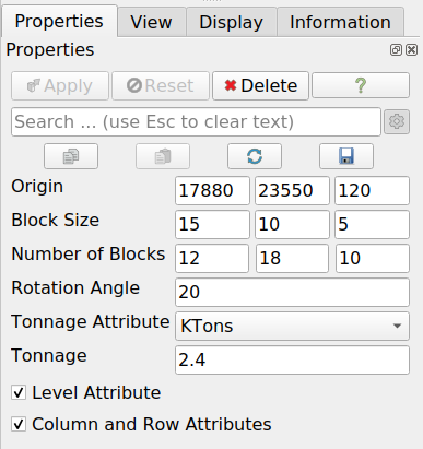
Fig. 3.1 Properties for defining an empty block model
On pressing Apply, the block model will be generated and shown in an AthosGEO Render View (3D View): see Fig. 3.2.
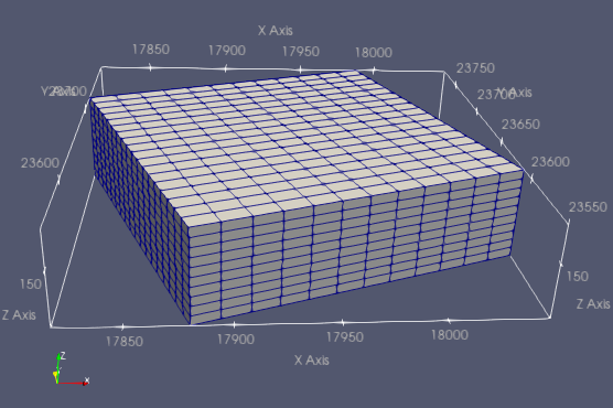
Fig. 3.2 An empty block model, meaning just blocks without attributes
It is now possible to manually generate attributes by using different filters, like:
Write Value or Write Multiple Values for manually assigning single values to selected blocks
Read Attributes from a File and Assign to Unstructured Grid if attributes are available in an existing file
Calculator or Calculator for Selection, as soon as some other attributes do exist
The following filters will allow to clip the block model to a specific shape:
Clip Model with Surface or Clip Model with GeoTiff for applying a top (topo surface) or bottom to the model.
Clip Model with Boundary for applying a bounary to the model like a cookie cutter.
Note
The latter filters will keep blocks that are only partially inside the desired volume and add a VolFactor attribute to all blocks, indicating the percentage of the block that is considered to be inside of the model.
3.3. Reading a Simple Block Model from a CSV File
Normally a block model is only useful if it has attributes assigned to the single blocks. Such a block model with attributes can be generated in many different ways depending on the input data and available softwares, written into a CSV file and from there directly converted into a block model. A very simple example of such a CSV file could be a table like this one: Table 3.1
X |
Y |
Z |
dX |
dY |
dZ |
Unit |
CaO |
|---|---|---|---|---|---|---|---|
1010 |
2010 |
205 |
20 |
20 |
10 |
LowerLst |
52.0 |
1030 |
2010 |
205 |
20 |
20 |
10 |
LowerLst |
52.3 |
1010 |
2030 |
204 |
20 |
20 |
8 |
LowerLst |
51.9 |
1030 |
2030 |
204 |
20 |
20 |
8 |
LowerLst |
52.1 |
1010 |
2010 |
213 |
20 |
20 |
6 |
LowerLst |
52.3 |
1030 |
2010 |
213 |
20 |
20 |
6 |
HigherLst |
48.7 |
1010 |
2030 |
211 |
20 |
20 |
6 |
HigherLst |
48.6 |
1030 |
2030 |
211 |
20 |
20 |
6 |
HigherLst |
48.7 |
In order to visualize this block model using AthosGEO View, you need to save it as a CSV file and open it with AthosGEO View with the block model reader, see Fig. 3.3
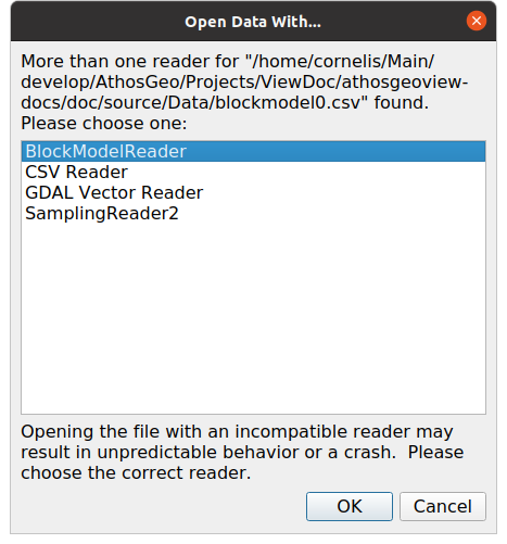
Fig. 3.3 On opening a CSV file, the user will see a choice of several possible readers
With this, the Properties panel will appear, see Fig. 3.4
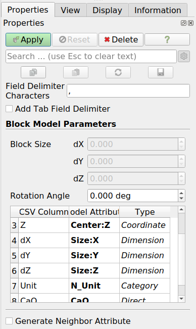
Fig. 3.4 Properties panel for the Block Model Reader
The section of primary interest is about Block Model Parameters: Block Size (dX, dY, dZ) and Angle, which is an azimuth angle, counting in degrees from N via E to S and W. Both can be
either specified within the table, such as above. In this case it is possible to specify block sizes or azimuth angles for every single block
or specified in the panel. In that case these are global values, to be applied to all the blocks equally.
At the bottom there is another property that can be activated: Generate Neighbor Attribute. This is only of interest for users of the cement specific modules of AthosGEO Blend. For users of AthosGEO View it is unimportant.
After pressing the Apply button, the block model can be displayed in the AthosGEO Render View with coloring according to the two defined attributes, as can be seen in Fig. 3.5 and Fig. 3.6
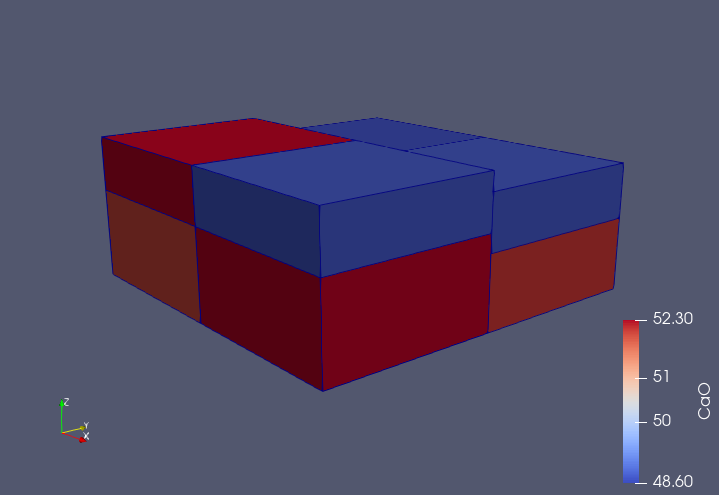
Fig. 3.5 Simple block model example displayed in an AthosGEO View Render View, with coloring according to the CaO attribute
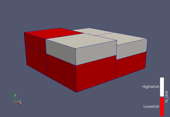
Fig. 3.6 Simple block model example displayed in an AthosGEO View Render View, with coloring according to the Units attribute
Hint
There are two ways to generate a block model from attributes in a CSV file (table), and you will use the one or the other depending on what kind of information you have in the table to specify the blocks:
For each block, centroid coordinates, block dimensions and if required a rotation angle are present as attributes: Reading a Simple Block Model from a CSV File.
For each block, a BlockId attribute is present: Generating an Empty Block Model, adding the actual attributes with the Read Attributes from a File and Assign to Unstructured Grid filter.
3.4. Block Model Attributes
For the naming of block model attributes in AthosGEO View conventions do apply, allowing the program to handle them accordingly, as coordinates, dimensions, tonnages, quality data, category names and many more. For the import from a CSV file, additional names are possible that are automatically converted into the standard names for convenience.
Please refer to Attribute Conventions for more details about this subject.
3.5. Saving a Block Model
Once a block model is imported as explained above, it can be saved in one of two possible ways: As a CSV file or as a VTK Unstructured Grid file (*.vtu). The following sections will explain the implications of these two options.
Many more formats are possible and can be relevant for the data exchange with other softwares.
3.5.1. Save as VTK Unstructured Grid (VTU) File
Saving as VTU file is the most straightforward way to save a block model in some kind of “native” ParaView format. A number of options can be chosen, as shown in Fig. 3.7
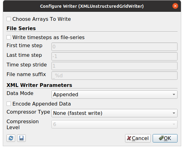
Fig. 3.7 Options for the Unstructured Grid Writer
The XML Writer Parameters are about compression. Go for Data Mode Binary and Compressor Type LZMA for smallest file size, or Ascii and None if you want a full plain text format, but if neither the one nor the other are of interest, this choice is not crucial.
In order to save an animation as a series of VTU files, the Write timesteps as file-series option needs to be checked.
3.5.2. Save as CSV File
A block model can be generated from a CSV file as described above in Section 3.3, and it can also be written back into a CSV file in such a way that reading it back into AthosGEO View is possible.
With this it is possible to manipulate the block model data with any spreadsheet program.
It is important to change the Precision in the CSV Writer Parameters dialog to something much larger than the default of 5, in order to get the centroid coordinates written with sufficient numeric precision: see Fig. 3.8
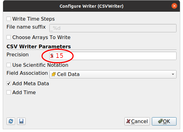
Fig. 3.8 Options for the CSV writer. In order to save a block model to a CSV file, Precision should be much more than 5 and Field Association must be Cells
The Field Association must be Cells because these are the actual blocks with the attributes.
Hint
Writing and reading a CSV file takes longer than the same operations for generic VTU files, so saving as CSV file makes only sense if manipulation is indeed the intention.
3.6. Viewing Block Models
Block models can be viewed with AthosGEO View in a 3D View (AthosGeo Render View) or as a numeric table (AthogGeo Table View), and analyzed with a great number of filters coming either from ParaView or from AthosGEO View.
Refer to Display a Block Model of the Reference Manual for more.