4. Manipulating Block Model Attributes
The following refers to manipulating attributes of block models, but it can be applied also to sampling sets (see Display Sampling Set) and to triangulated surfaces or polylines (see Display a Topo).
Preliminary Remark
The primary purposes of ParaView are data visualization and data analysis. This is also the focus of the underlying VTK (Visualization Toolkit), and AthosGEO View inherits this focus as well. The basic data and models (like the block models) have to be prepared with other tools. The pipeline of filters is a perfect concept for this kind of functionality.
However, the pipeline of filters is far less suitable for cases where data need to be interactively changed or edited within a software. Still it is in certain cases desirable or even required to do it in AthosGEO View. So in order to fit into the working principle of the software, each and every editing step has to be a filter, and if a second editing step follows the first, another filter must be added to the processing pipeline, and so on.
4.1. Calculator  
The Calculator filter takes a data set with attributes as input and calculates a new attribute by applying a formula that can be entered in the Properties panel (see Fig. 4.1), or it overwrites an existing attribute.
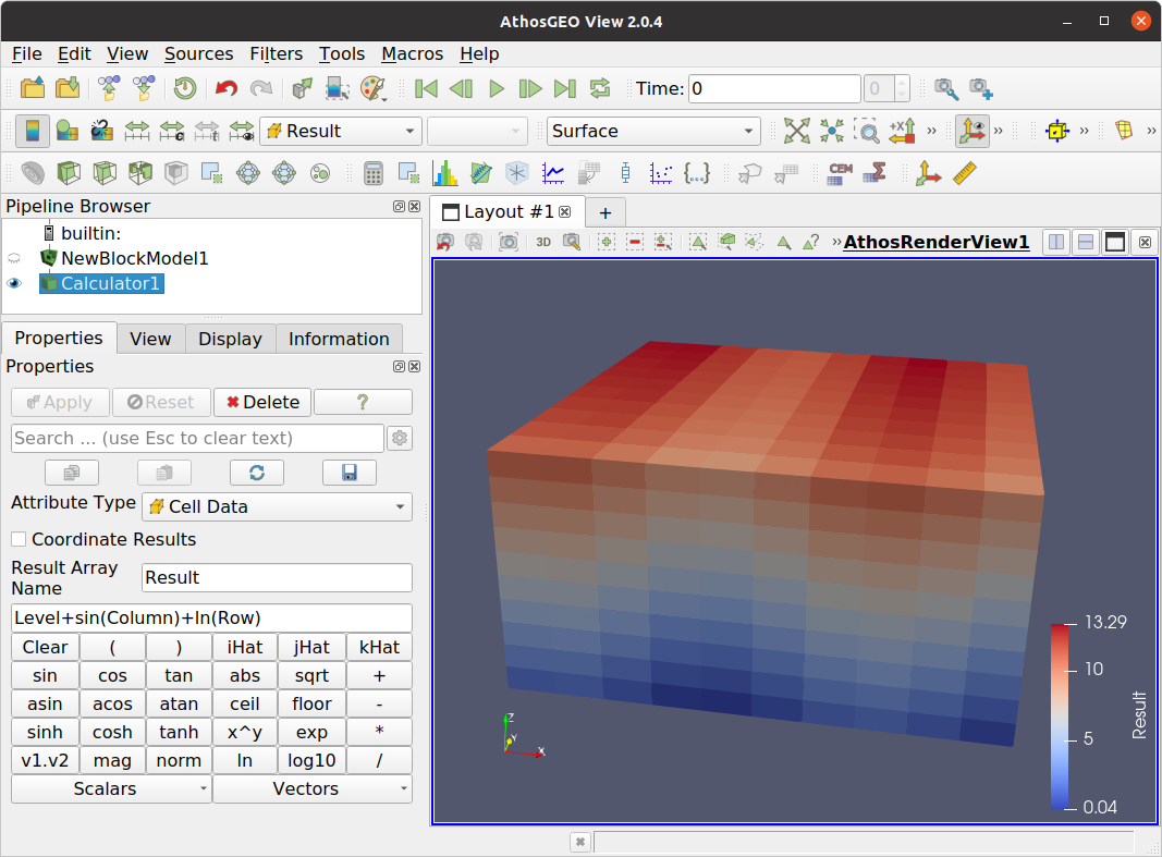
Fig. 4.1 Properties of the Calculator filter
In the example in Fig. 4.1, pressing Apply will generate a new attribute Result in the Cell Data of the data set.
4.2. Calculator for Selection  
Sometimes it is not desirable to apply a formula to all the blocks in a model. For this case, AthosGEO View comes with another calculator filter: Calculator for Selection - see example in Fig. 4.2.
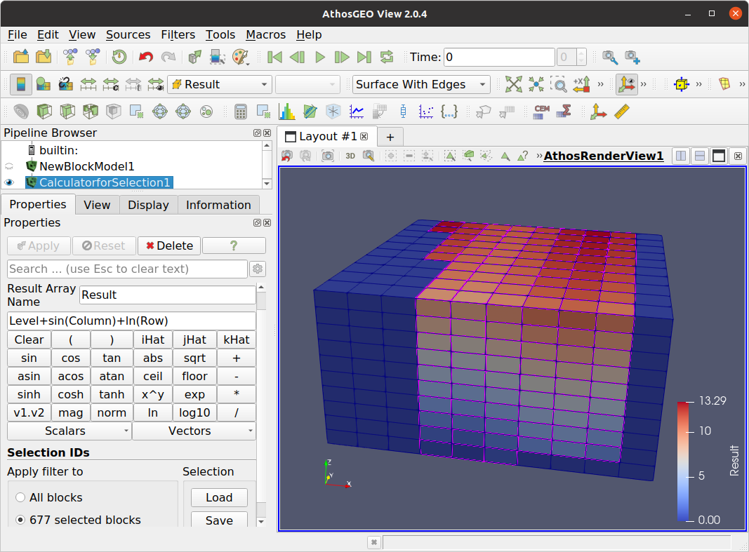
Fig. 4.2 With the Calculator for Selection filter, calculations are only applied to the selected blocks in the block model
In order to apply this Calculator for Selection filter, the following steps are required in this order. Regarding selections, see also Selections for Attribute Manipulation.
Choose the Calculator for Selection by pressing
Select the blocks to which the calculations should be applied. Please refer to Section 6 for more information about how to select blocks.
Enter the desired result array name and the formula and press the Apply button.
Note
As with the Calculator filter, also the Calculator for Selection can either generate a new attribute or overwrite an existing one. But what happens with the cells that are not selected in these two cases?
If the result attribute is new, the Replacement Value will be assigned to all the non-selected model blocks.
If the result array already exists, values for the non-selected model blocks will remain unchanged.
Note that the Replacement Value is only visible in the advanced mode of the properties panel, and it exists for both calculator filters because that value will also be assigned where the formula results in an error condition, like a division by zero.
4.3. Write Value  
The Write Value filter cannot do anything that the Calculator for Selection is not able to do as well (see Section 4.2). The only purpose is convenience for the case that the formula would be only one constant number. The functionality is very simple, as can be seen in Fig. 4.3: A new attribute is generated and a value is assigned to the selected blocks. Regarding selections, see also Selections for Attribute Manipulation.
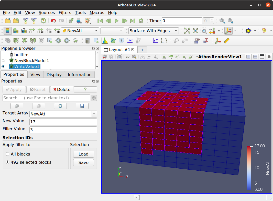
Fig. 4.3 Example of the Write Value filter: The Target Array is new, so the filter will generate it as a new attribute. The New Value is assigned to the selected blocks, and the Filler Value is assigned to all other blocks
If another value for the same new attribute has to be assigned to another set of blocks, a second instance of the Write Value filter must be appended to the pipeline, as shown in Fig. 4.4.
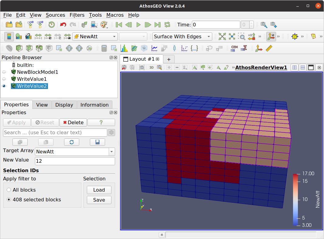
Fig. 4.4 For the second instance of the Write Value filter, the NewAtt attribute is not new any more, so the properties panel does not show a Filler Value property any more: All non-selected blocks will simply remain untouched. Selected blocks will receive the newly specified value.
4.4. Write Multiple Values  
Also the Write Multiple Values filter is a convenience filter that is able to do in one single step the two steps that are described for the Write Values (see Section 4.3). It also either generates a new attribute or manipulates an existing one, but it is able to write more than one single value, as shown in Fig. 4.5. Regarding selections, see also Selections for Attribute Manipulation.
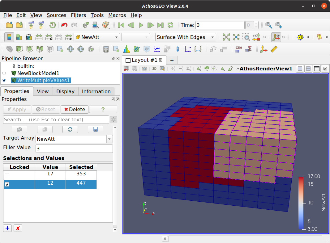
Fig. 4.5 With the Write Multiple Values filter, more than one value can be written into a new or an existing attribute.
Note
The Write Multiple Values filter needs to manage multiple selections in order to do it’s job: Every row of the Selections and Values has one set of selected blocks, and making the one or other active will show or hide that selection in the view.
4.5. Remove Data Arrays  
It’s a bit confusing: If somebody looks in ParaView for a filter that removes the one or other not any more required attribute, nothing can be found! But this is only a question of wording: The name of the filter is Pass Arrays. The only difference to a non existing Remove Arrays filter is the fact that the user selects not the arrays to be removed, but the arrays to be passed. As a result, the effect is exactly the same!
4.6. How to Manipulate the Inner Blocks of a Model
In the Surface or Surface with Edges representation of a Render View, only the outer blocks of a block model are visible, but manual selection that is required for the different value manipulation filters described in this chapter (see Section 4.2, Section 4.3 and Section 4.4) is hardly possible for inner blocks.
This is where the Category or the Category with Edges representation will be helpful. First it is of course important to have a Category attribute in the model like Level. The procedure is explained with a series of figures from Fig. 4.6 to Fig. 4.12.
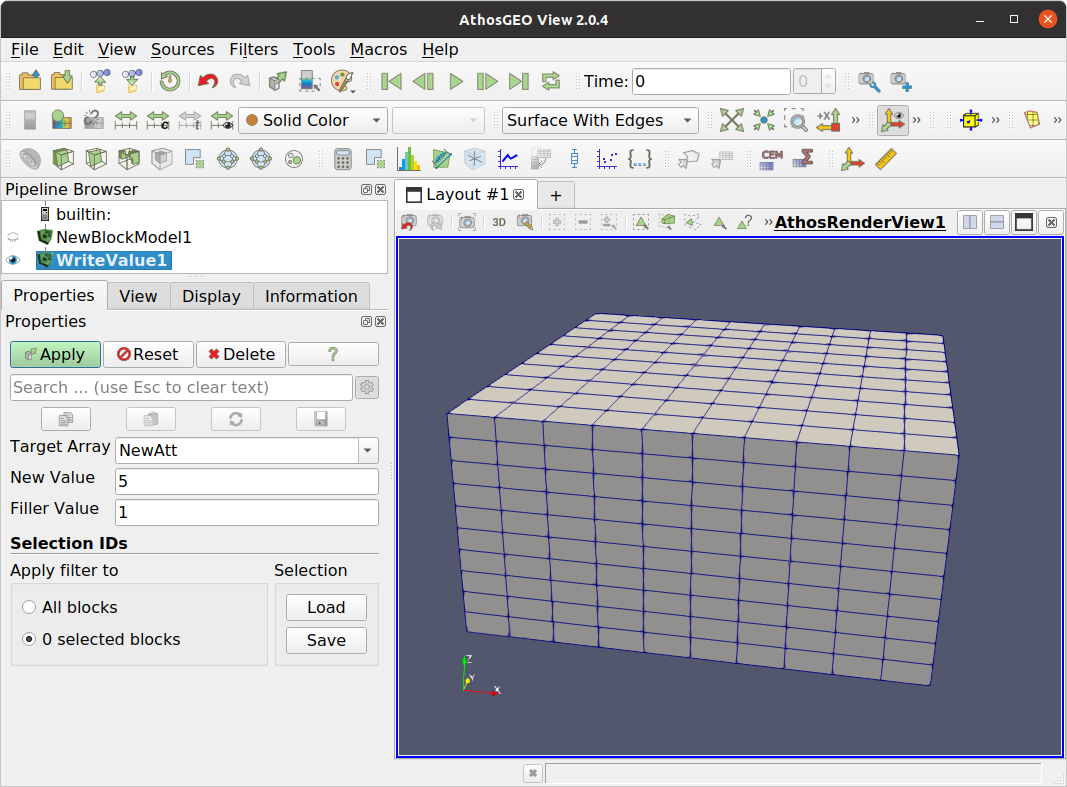
Fig. 4.6 As a first step in this example, the Write Value filter is activated.
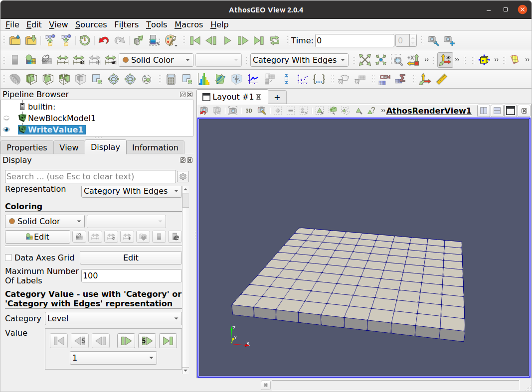
Fig. 4.7 Next, the Category with Edges representation is selected and in the Display tab of the properties panel, the Level attribute is selected for the display.
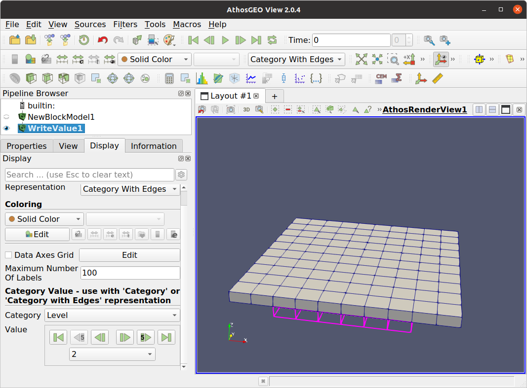
Fig. 4.8 A number of blocks were selected at level 1, then from the Display panel the Level was changed to level 2. Note that the selection at the lower level remains visible.
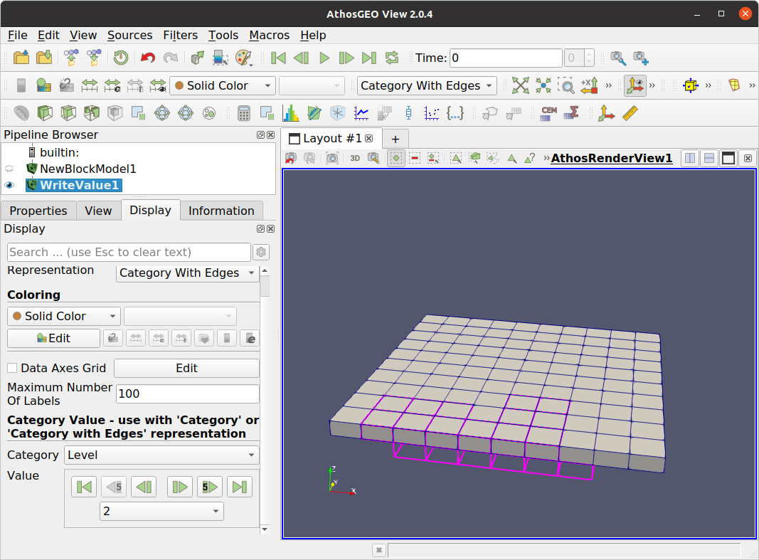
Fig. 4.9 With the + button turned on in the selection tool bar at the top of the view, another group of blocks is selected at level 2.
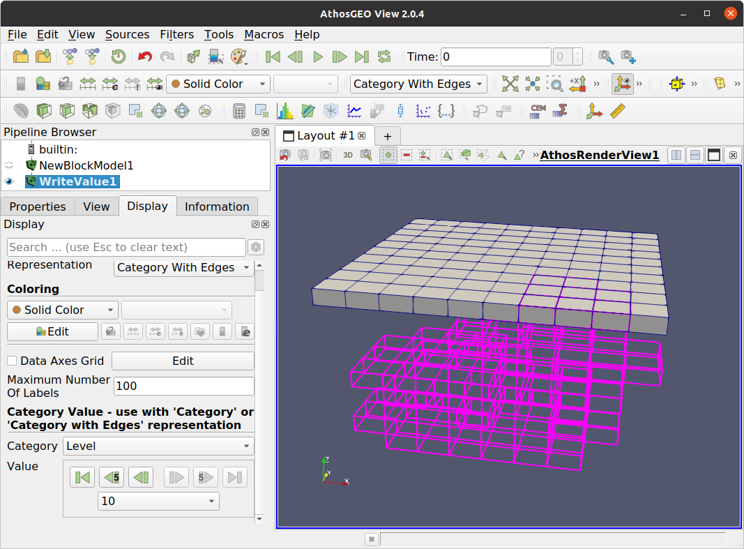
Fig. 4.10 A few levels later, an entire selection of blocks in 3D space is finished. Hint: Make sure to do this from bottom to top (in this specific case), because otherwise it is difficult to do the proper block selections “through” the already existing selection indicators.
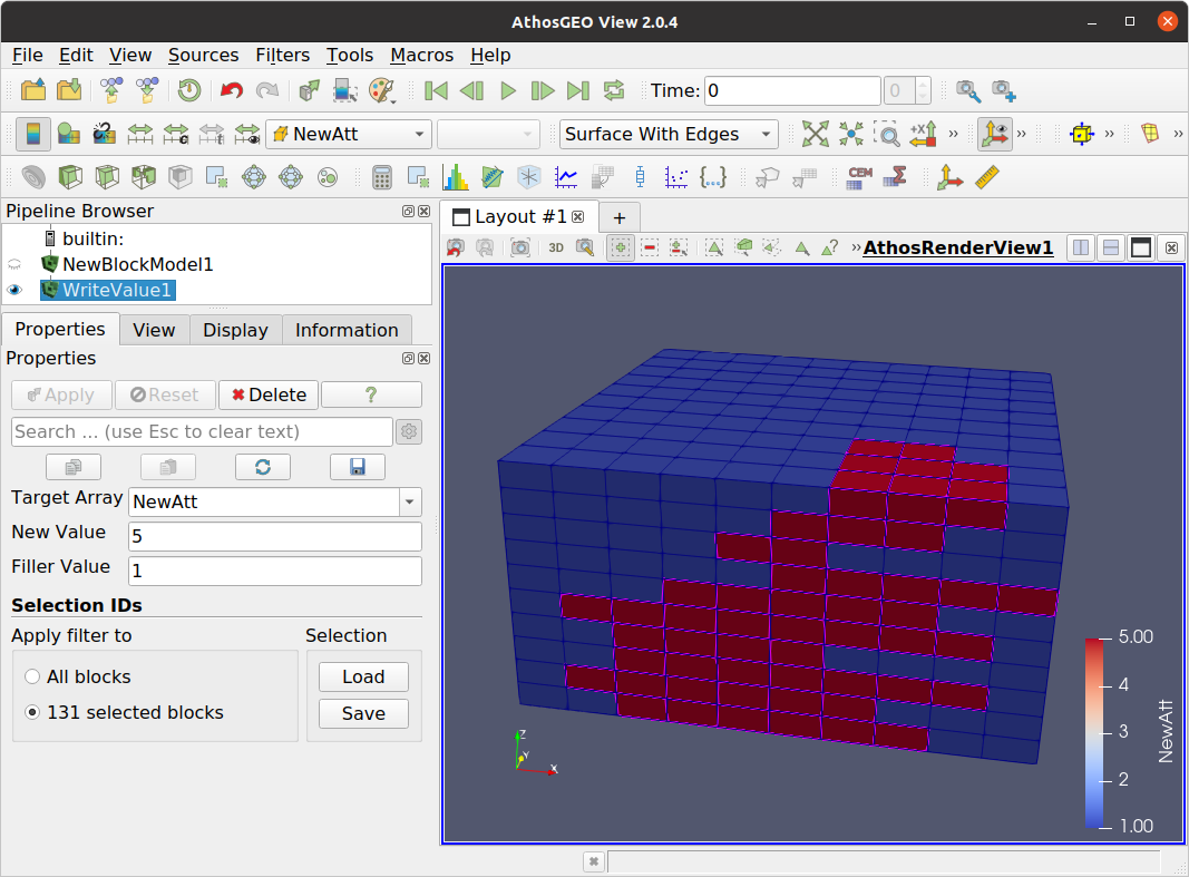
Fig. 4.11 After pressing Apply and switching back to a Surface with Edges representation shows the result of the action.
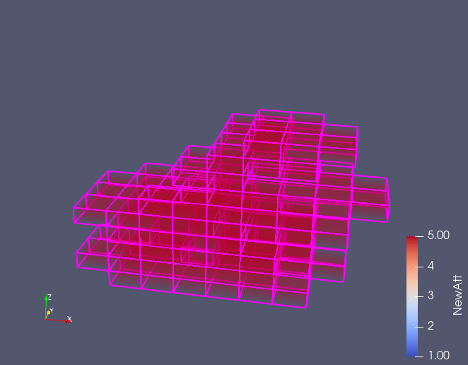
Fig. 4.12 The same thing as a Volume representation where the full spacial extent becomes visible.
4.7. Models with Unequal Block Heights
Sometimes it makes sense to design a block model in such a way that blocks would follow geological units. This can be achieved with blocks always covering such a unit in vertical direction.
Note
A model with blocks following geological units is of special interest for users of AthosGEO Blend with a quarry where mining follows these units, in order to maximize the blending opportunities.
With the following the generation of such a block model will be described. The starting point is illustrated with a schematic geologic cross section as shown in Fig. 4.13.
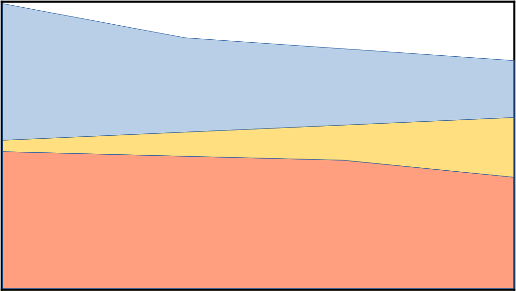
Fig. 4.13 Cross section with geological section. The intention is to follow these units during mining, and in order to reflect in the planning, we want the blocks of the model to follow the geology.
AthosGEO View and AthosGEO Blend are not able to do geostatistics for the generation of a block model. Other tools can do it, but they are normally not able to do what we are trying to achieve here. What can be done is the generation of a model with very “flat” blocks, like 1m or 2m only. And it is possible to assign some code for the geological units that are dominating within each one of the blocks, as shown in Fig. 4.14.
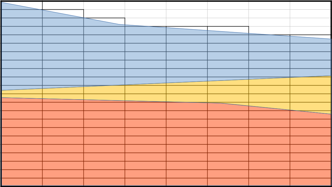
Fig. 4.14 Tools to calculate block models will normally not generate models that follow geological units, but it is possible to generate models with rather flat blocks, with a vertical dimension of only 1m or 2m, as a first step.
Before AthosGEO View can now merge blocks within the same geological unit vertically, theses blocks need to be marked accordingly, like with a Code attribute that assigns a number to every block, indicating which unit it mostly belongs to. This would normally still be part of the block model generatin step, and the result would be a block model as shown in Fig. 4.15.

Fig. 4.15 In order to merge the flat blocks according to geological units, an attribute of category type is required, like Code, Geology etc.
Now is the time to apply the Merge Blocks by Category filter. In the Properties panel it will ask for selecting one available attribute of attribute type category (see Section 6 regarding attribute types). The result will be a block model with blocks that approximately follow the geological units, as shown in Fig. 4.16.
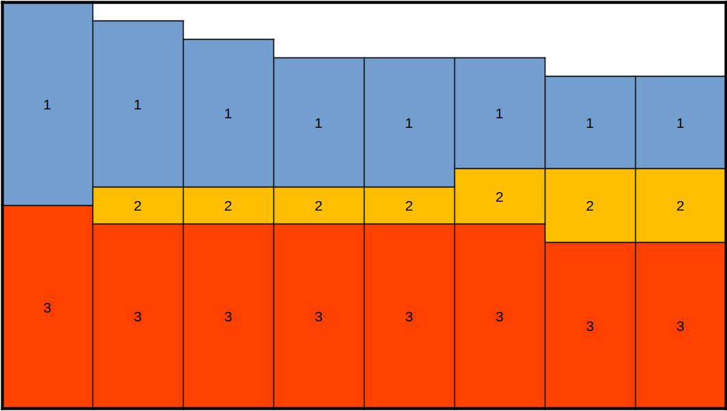
Fig. 4.16 After application of the Merge Blocks by Category filter, this will be the output. Note that block merging will only happen in vertical direction.
4.7.1. Attributes
So far this was about geometry. Next we still need to cover what happens with the attributes. Basically, attributes of the new merged blocks are calculated following the strategy of the Summary Table, as described here in Section 3.2.
However, there are two differences regarding attributes of type category:
The category type attribute that is the base of the block merging is of course maintained in the output.
Additional attributes will optionally be generated, indicating the percentage of material with a specific attribute value within every generated merged block.
The second feature will require some additional explanation, both about the purpose of this feature and the way how it is calculated. Both can best be done with an example.
The properties panel of the MergeBlocksByCategory filter allows to specify two properties (see Fig. 4.17):
One category attribute that will guide the block merging - Code in the example
Optionally one or several category attributes for the generation of new category value attributes - again Code in the example.
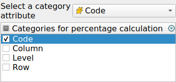
Fig. 4.17 The Properties panel of the MergeBlocksByCategory filter allows the selection of one category attribute that guides the merging. Additionally and optionally it is possible to select one or several category attributes for the generation of new category value attributes.
The result of the merging can be seen in Fig. 4.18:
The block’s vertical extent follows the Code values.
Four new attributes were generated, for every existing value of the Code attribute:
C_Code_0
C_Code_1
C_Code_2
C_Code_3
The values of this attribute can only be 0 or 100% in this case, because every new block is made up of always only one unique Code attribute value.
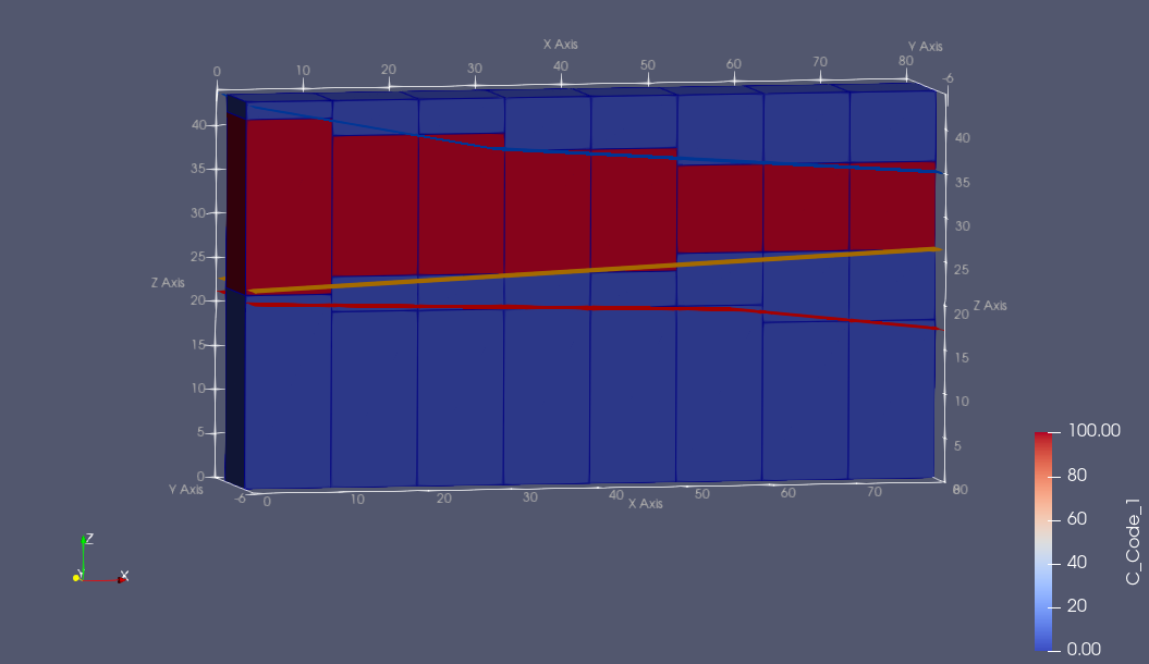
Fig. 4.18 Result of block merging by Code attribute values. Coloring shows all blocks in red that are 100% made up of material where this value is 1, while all others are blue, indicating 0%.
It is also possible to choose another category attribute for the generation of new percentage attributes: see Fig. 4.19 for an example where Level was selected.
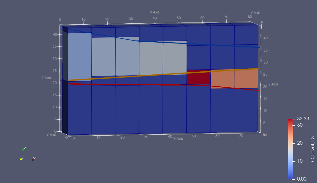
Fig. 4.19 This the result of merging the blocks by Code and calculating new attributes indicating the amount of material within a specific original Level. The coloring shows the percentage of each block that is from level 13.
Note
This last example with the level percentage is a bit artificial, with little practical use, but it illustrates the functionality.
The purpose of having such kind of percentage attributes is for mixing calculations. Assume that a subset of blocks within the model is selected, like the production of one year, such attributes will allow to directly see how many percent of the selected set is from Code value 1, 2, 3 etc., and the same in the above example also with Level value 1, 2, 3 etc. And if there was a category attribute Quarry in a multi-quarry model, also the proportion from Quarry A, B and C etc. can be directly seen.
Note
Use this function with care, because if a category attribute has many used values, it generates a huge number of attributes!
It is possible to achieve a slightly more precise result if the type of category value attributes is prepared already before the merging, e.g. during the block model generation. In Fig. 4.20 it is shown how already the “flat” blocks are having a C_Code_1 attribute that was calculated from the block fraction below and above the blue and yellow surfaces.
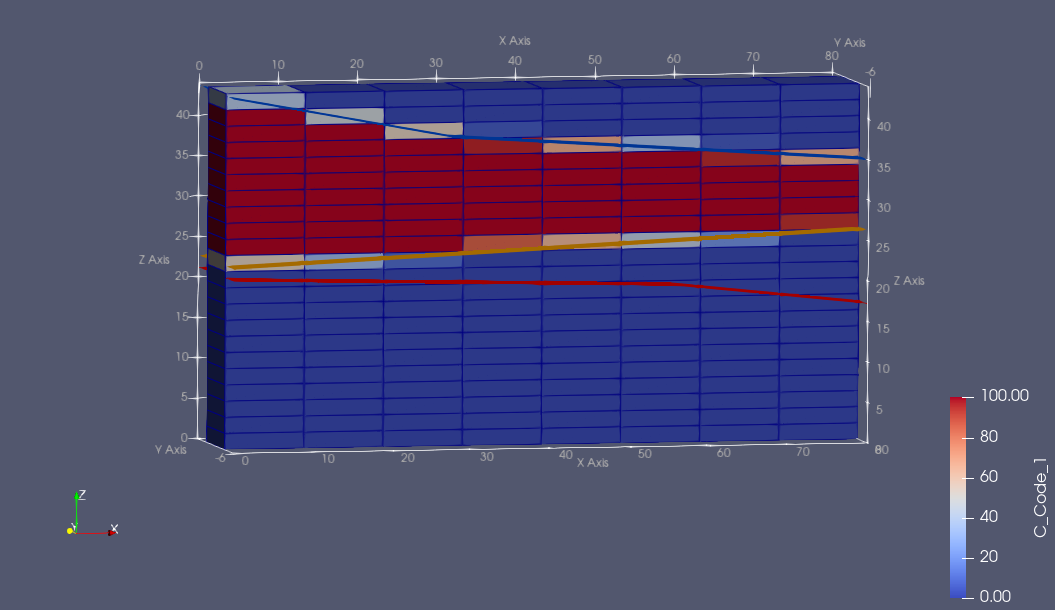
Fig. 4.20 In this model is already a C_Code_1 attribute indicating the percentage of “Code = 1” material within every “flat” block (plus another attribute for each other Code value). Such attribuges can be generated in many ways, either within AthosGEO View or with other softwares.
In oder to use the existing C_Code_n attributes during the merging process, the Code attribute must not be checked in the Categories for percentage calculation list in the Properties panel. In this case, these attributes are dealt with according the rules for Direct type attributes: calculate the tonnage weighted mean. The result looks like shown in Fig. 4.21: Blocks are not any more either 0 or 100%, but can include “impurities” from the neighboring Code zone.
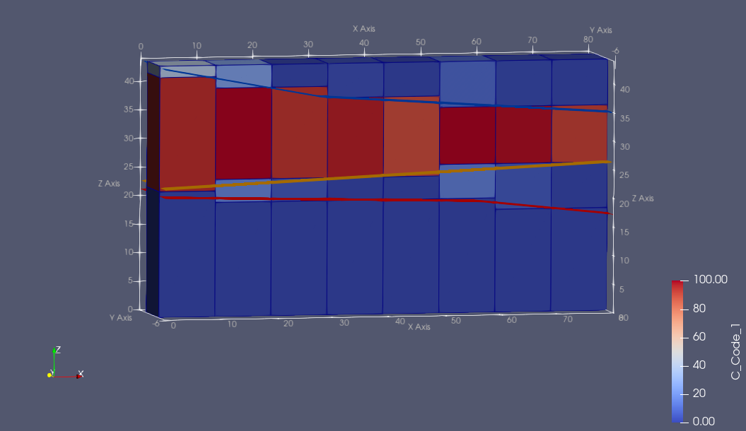
Fig. 4.21 In this variant, the C_Code_n attributes of the block merging result are indicating also little amounts of “contaminations” from neighboring Code value zones.
Note
For this last hint to work, it is of course not required to follow the naming scheme like C_Code_n, but any valid attribute name can be used, as long as it follows the pattern for Direct type attributes.