5. Sampling Set Basics
5.1. Definition and Purpose
In very general terms, a sampling set is
A series of georeferenced sample data, i.e. samples with labels, laboratory results and coordinates (x, y, z).
A data set from a drilling campaign, again with labels, laboratory results and coordinates, often stored in 3 tables:
- asset
laboratory data with drillhole and sample labels and depth ranges within the drill hole
- collar
list of drillholes with drillhole labels, coordinates of the hole top points and typically also characteristic of the drillhole, e.g. “linear”
- survey
geometric drillhole descriptions with drillhole labels, depth, dip and azimuth angles
In simple cases, the drillhole data can be delivered with less tables - details see below.
The intention of loading sampling sets into AthosGEO View is the display of point or linear symbols in order to visualize quality raw data of a survey.
Hint
Sampling sets are typically the input data for calculating block models (see Block Model Basics) with methods of geostatistics.
Please note that geostatistics is NOT part of the AthosGEO View software.
5.2. Reading Sample Data from a CSV File
In the case of plain georeferenced sample data, only one CSV file it required for input. Table 5.1 would be a minimal example.
SampleID |
X |
Y |
Z |
SiO2 |
CaO |
|---|---|---|---|---|---|
Sample 1 |
41226 |
25732 |
412 |
9.8 |
48.2 |
Sample 2 |
52332 |
20158 |
396 |
28.2 |
32.4 |
Sample 3 |
46298 |
29647 |
422 |
8.7 |
50.1 |
In order to visualize thess samples using AthosGEO View, you need to save this table as a CSV file and open it with AthosGEO View with the block model reader, see Fig. 5.1
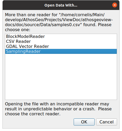
Fig. 5.1 The Samples Reader interprets the content of a CSV file as either a number of single samples or as the assay file of a drilling campaign
With this, the Properties panel will appear as in Fig. 5.2
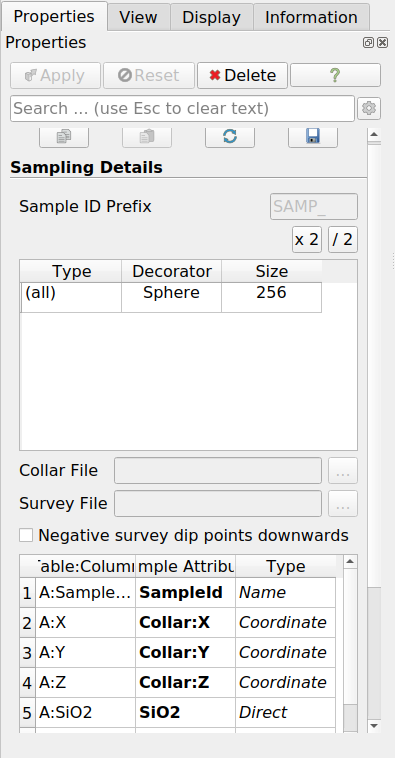
Fig. 5.2 Properties panel for the Samples Reader
In the Sampling Details section it is possible to specify some parameters for the display of the samples.
If the input table does not come with a Sample ID column, a sample ID will be automatically generated from a prefix that can be specified in the Sample ID Prefix property and a numeric counter.
The table within this section is about display of the samples:
- Type
If the input table has a Holetype column, the different hole types will be listed, so they can be assigned different location markers and sizes. If such a column does not exist, it will be (all).
- Decorator
With a click into a cell within this column, a decorator or little 3D object can be chosen to mark the sample locations in space.
- Size
With this, the relative size of the decorator within the 3D view can be determined.
Note
The Type feature in the Sampling Details table was introduced for drilling campaigns originally, which is also the reason for the naming of the column. See the list of possible point sample decorators in Fig. 5.3.
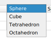
Fig. 5.3 Possible sample point decorators
Note
The two little buttons x 2 and / 2 can be used to increase or decrease all size values by a factor of 2.
The section of primary interest is about Block Model Parameters: Block Size (dX, dY, dZ) and Angle, which is an azimuth angle, counting in degrees from N via E to S and W. Both can be
either specified within the table, such as above. In this case it is possible to specify block sizes or azimuth angles for every single block
or specified in the panel. In that case these are global values, to be applied to all the blocks equally.
After pressing the Apply button, the samples can be displayed in the AthosGEO Render View with coloring according to the two defined attributes, see Fig. 5.4
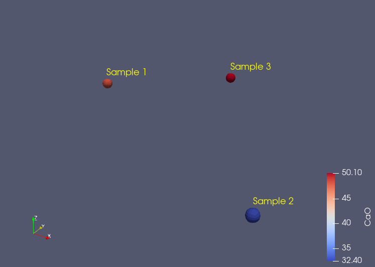
Fig. 5.4 Samples example displayed in an AthosGEO View Render View, with coloring according to the CaO attribute
Note
Sizing of the 3D symbols is not automatic, so if no 3D symbols do appear, the size should be increased manually. Again press Apply to see the effect.
Note
Normally, reading a data item in AthosGEO View will generate one display item in the Pipeline Browser, but the SamplingReader generates two, as shown in Fig. 5.5
- Samplings
The sampling data objects themselves, with attributes that can be chosen for coloring
- Sampling Labels
Labels next to the data objects that can be shown or hidden independently
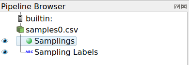
Fig. 5.5 Pipeline browser for a sampling, showing Samplings and Sampling Labels
5.3. Reading a Drilling Campaign from CSV Files
A typical drilling campaign data set comes with 3 tables, as specivied above (Section 5.1). In order to read these data into AthosGEO View, these tables need to be stored in CSV files, with the assay being mandatory and collar and survey being optional, if the required data are provided in the assay already.
The assay is what would be selected with the Open command, and a little example would look like shown in Table 5.2
HoleID |
SampleID |
DepthFrom |
DepthTo |
CaO |
SiO2 |
|---|---|---|---|---|---|
Hole 1 |
Sample 1 |
0 |
22 |
47.6 |
5.2 |
Hole 1 |
Sample 2 |
22 |
38 |
25.9 |
24.8 |
Hole 2 |
Sample 3 |
0 |
18 |
50.2 |
4.8 |
Hole 2 |
Sample 4 |
18 |
37 |
44.6 |
5.8 |
Hole 2 |
Sample 5 |
37 |
55 |
22.4 |
26.1 |
At this point, the Properties panel will appear as shown in Fig. 5.6. Within this panel, Collar File and Survey File need to be selected, as shown in Table 5.3 and Table 5.4.
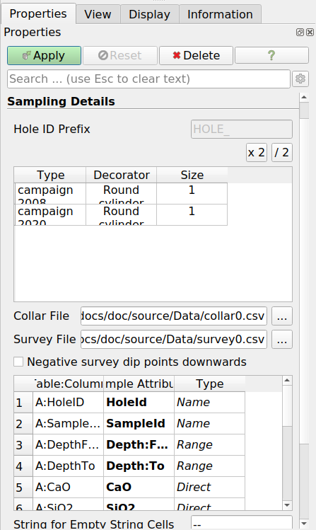
Fig. 5.6 Properties panel of the samples reader
HoleID |
X |
Y |
Z |
HoleType |
|---|---|---|---|---|
Hole 1 |
42662 |
16524 |
460 |
campaign 2008 |
Hole 2 |
42498 |
16766 |
455 |
campaign 2020 |
HoleID |
Azimuth |
Dip |
|---|---|---|
Hole 1 |
130 |
45 |
Hole 2 |
0 |
90 |
Note
The Type feature in the Samplings Details table lists the HoleType attribute from the collar table. To each one of these types, another Decorator can be assigned. See the list of possible drill hole decorators in Fig. 5.7.
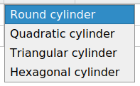
Fig. 5.7 Possible drillhole decorators
On pressing the Apply button, the AthosGEO Render View (3D view) will show the drillholes as colored cylinders as in Fig. 5.8
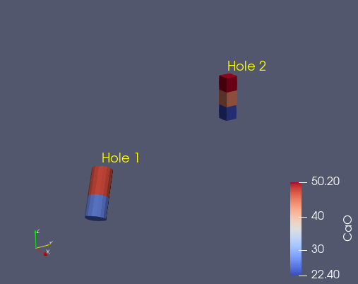
Fig. 5.8 Drillholes example displayed in an AthosGEO View Render View, with coloring according to the CaO attribute
Did you know?
The way how AthosGEO View will distinguish between a Set of Single Samples and a Drilling Campaign Data Set is with the HoleID attribute: If it does not exist, it is not a drilling campaign.
5.4. Sampling Set Attributes
Please refer to the Block Model Attributes section of Block Model Basics which applies also to the attributes of sampling sets.
5.5. Viewing Sampling Sets
Sampling sets can be viewed with AthosGEO View in a 3D View (AthosGeo Render View) or as a numeric table (AthogGeo Table View), and analyzed with a great number of filters coming either from ParaView or from AthosGEO View.
Refer to Display Sampling Set of the Reference Manual for more.