5. Clipping, Cutting, Merging and Extracting
5.1. Functions and Limitations
AthosGEO View is a viewer in the first place. In Section 4 it was described how attributes can be manipulated. In this current chapter it will be about geometric manipulations of both block models and surfaces such as topos.
Three types of manipulations will be described:
Extracting parts of a geometry
Merging geometries
And the most complex subject: clipping and cutting geometries with other geometries
5.2. Extracting Parts of a Block Model or a Triangulated Surface
Extracting parts of a geometry is done in two steps:
First, select the parts to be extracted. Selections are a science in it’s own, so they are handled in an own chapter here: Section 6.
Second, use the Extract Selection
 filter
5.3. Merging Geometries
There are two filters that allow the merging of geometric objects, that are applicable depending on the input data type. In order to apply one of these two filters, we need to select the geometric objects to be merged in the Pipeline Browser, as shown in Fig. 5.9.
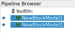
Fig. 5.9 More than one item can be selected in the pipeline browser by first clicking on the first, then hold down the CTRL key while clicking on additional items. Note that it is possible to select two or more items that way
Once a number of items are selected, the following two filters can be activated from the Filters → Alphabetical menu, depending on the VTK data or geometry types of the input data items:
Append Geometry
Append Dataset
Note
The Information panel is providing information about the VTK data or geometry type of a selected pipeline browser item.
5.3.1. Append Geometry
If all input items are of type Polygonal Mesh, it is possible to generate one merged polygonal mesh with the Append Geometry filter: see Fig. 5.10.
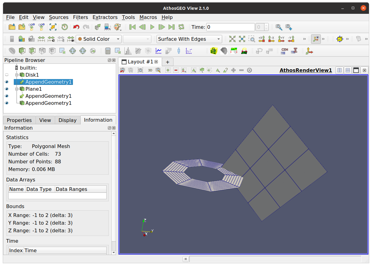
Fig. 5.10 Two or more Polygonal Mesh geometries can be merged into one single Polygonal Mesh with the application of the Append Geometry filter
5.3.2. Append Dataset
If one or several of the input pipeline browser items are of type Unstructured Grid, then the Append Dataset filter is able to merge these items into one single unstructured grid: see Fig. 5.11.
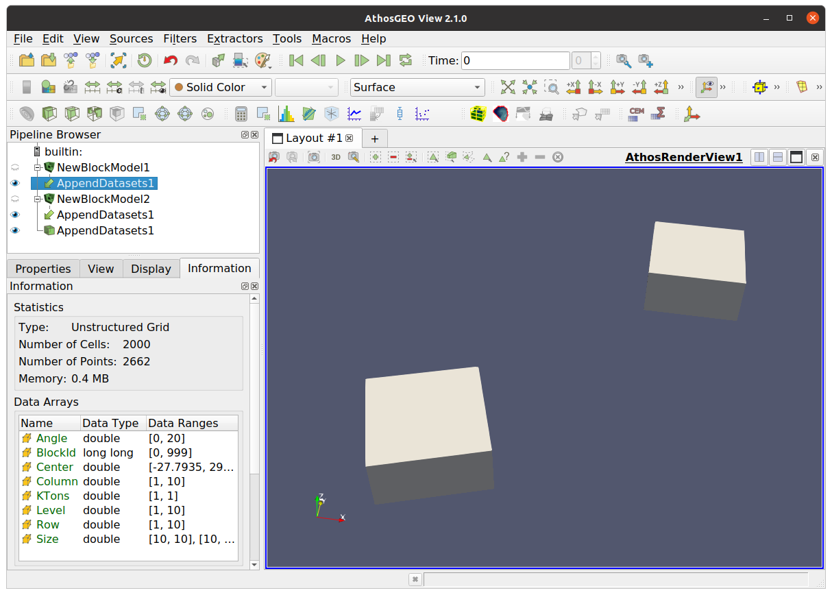
Fig. 5.11 Two or more Unstructured Grid and Polygonal Mesh geometries can be merged into one single Unstructured Grid with the application of the Append Datasets filter
Hint
To some degree, Unstructured Grid items can be “converted” into Polygonal Mesh items with the Extract Surface filter, but the result will not be a 1:1 equivalent. If the input unstructured grid is e.g. a block model, the output polygonal mesh will be a surface that represents the hull of the block model, without the volume filling.
5.3.3. Finalizing merged items
If merged surfaces or block models are actually adjoining each other, the merging process should be completed with the application of one of the Cleaning filters:
The Clean filter is for Polygonal Mesh data. Apply it in order to e.g. merge coinciding points at the boundary between the previously merged geometries
The Clean Cells to Grid filter does the same thing for Unstructured Grid objects like block models
Hint
The Clean to Grid filter does basically the same thing, but it will always generate an Unstructured Grid as output.
5.4. Clipping and Cutting
Clipping and cutting block models and surfaces are more complex operations, with different filters doing a similar job, but with a different focus. The following sections will deal with them in an order that is based on typical use cases:
Generic clipping of block models or surfaces
Clip Geometry
Manually shaping a manually generated block model
Clip Model with Boundary
Clip Model with Surface
Clip Model with GeoTiff
Cutting precise holes into a topo
Topo Cutter
Outline Block Model
5.4.1. Generic Clipping  
The Clip Geometry filter combines a number of functions into one filter, to allow clipping both block models and topo surfaces with both surfaces and boundary lines. The focus is on “getting it done” in a robust way, not on ensuring that the clipping is in all cases 100% perfact, no matter what the resolution (point density) of the input geometries is - see the examples below.
5.4.1.1. Clipping a Sphere (VTK type Poly Data) with a Plane (Poly Data)
The input geometries - sphere and plane - are shown in Fig. 5.12.
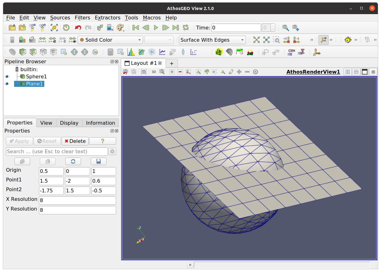
Fig. 5.12 A simple sphere that is intersected by a simple plane. The following images will illustrate the different options
Without any options, cells are not clipped, and only cells that are fully on one side of the clipping plane are kept in the output: Fig. 5.13.
With the Keep cells along boundary option turned on, also all those cells that are cut by the clipping plane will be kept in the output: Fig. 5.14.
The Invert output will invert the orientation of the clipping plane, while not inverting the effect of the Keep cells along boundary option: Fig. 5.15.
The Clip cells option will actually clip also the cells, generating new ones: Fig. 5.16.
Note that the Only cells along boundary option does not have an effect if the input is of type Poly Data, like the sphere in this example.
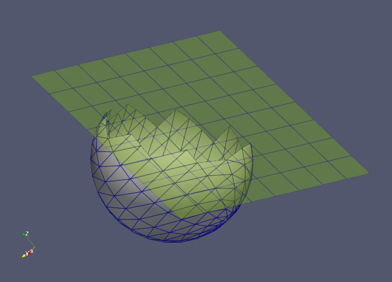
Fig. 5.13 All options are off
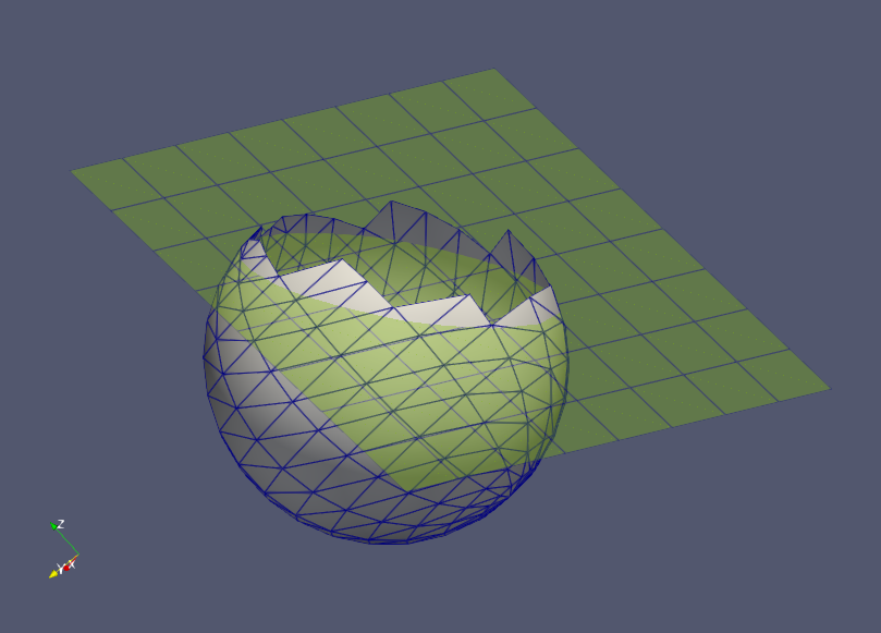
Fig. 5.14 With Keep cells along the boundary on, cells that are cut by the clipping plane, are kept in the output
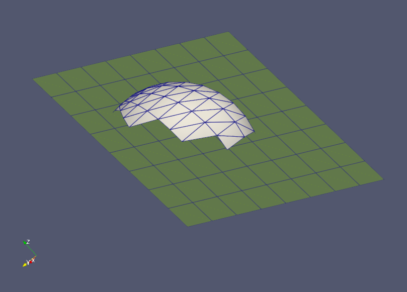
Fig. 5.15 The Invert output option will invert the orientation of the clipping plane. Note that the Keep cells along the boundary option is not affected by this option
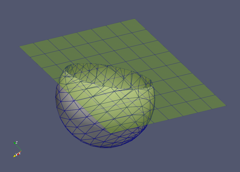
Fig. 5.16 The Clip cells option will clip the cells and generate new ones. However, it does not do an effort to ensure a 100% perfect cut along the clipping plane. The result largely depends on the resolution of the input geometries, so refining the triangulation will result in more precise clipping.
Clipping the sphere can also happen with a boundary line. That boundary line will be extended along the Z axis, like a “cookie cutter”:
Clipping the sphere without further options: Fig. 5.17.
The same thing with the Clip cells option turned on: Fig. 5.18.
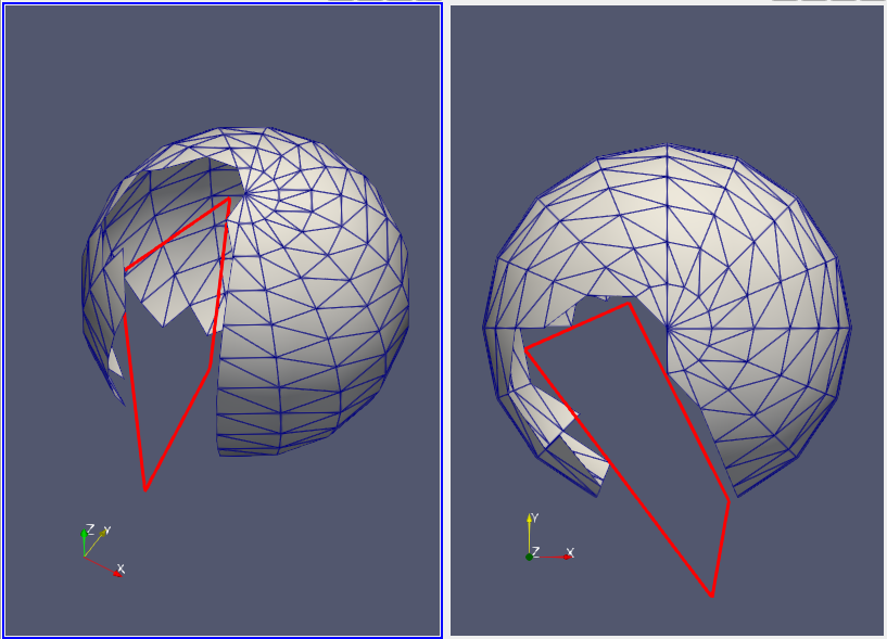
Fig. 5.17 Clipped the sphere with a boundary line results in a “cookie cutter” effect along the Z axis.
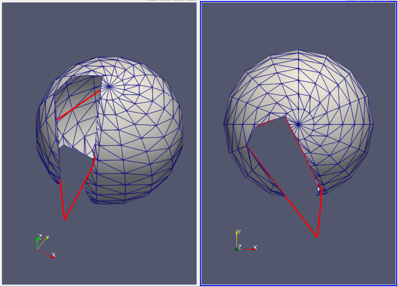
Fig. 5.18 Clipped the sphere with a boundary line results in a “cookie cutter” effect along the Z axis.
Hint
If precise “cookie cutting” is important, please have a look into the Precise Topo Cutting section.
For the following examples, a small block model (VTK type Unstructured Grid) will be clipped instead of the sphere of the previous examples:
All options turned off: Fig. 5.19
With the Keep cells along boundary option, blocks (cells) that are cut by the clipping plane are retained in the output: Fig. 5.20
The Invert output flips the orientation of the clipping plane (but not the effect of the Keep cells along boundary option): Fig. 5.21
For block models, the Keep only blocks along boundary option will only keep those blocks in the output that are cut by the clipping plane: Fig. 5.22
The Clip cells option, if applied to block models, will clip also those blocks (cells) that are cut by the clipping plane - with the effect, that they are not any more cuboids at the end: Fig. 5.23
Hint
The Clip Geometry filter clips a block model only geometrically, without taking attributes into account. If this is the intention, please have a look into the Shaping a Block Model section.
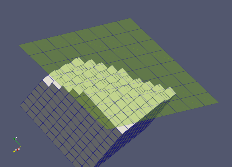
Fig. 5.19 Clipping a block model without further options
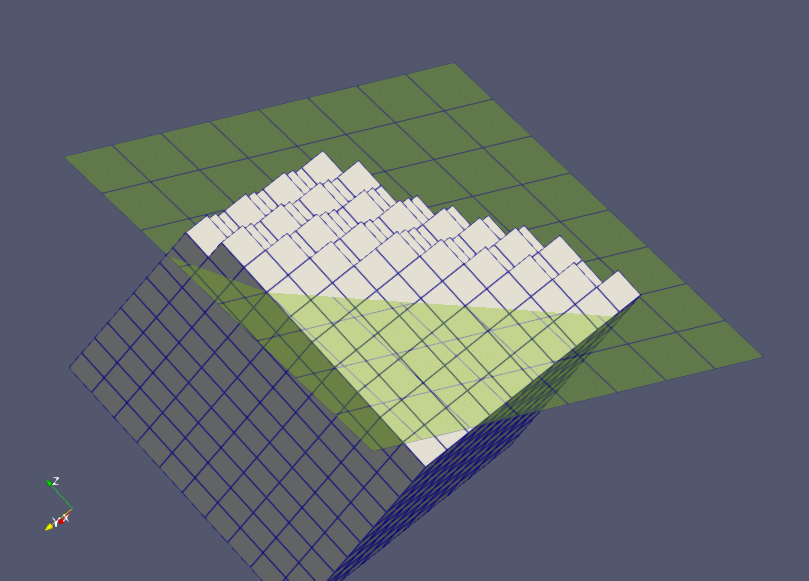
Fig. 5.20 Keep also the blocks (cells) that are cut by the clipping plane
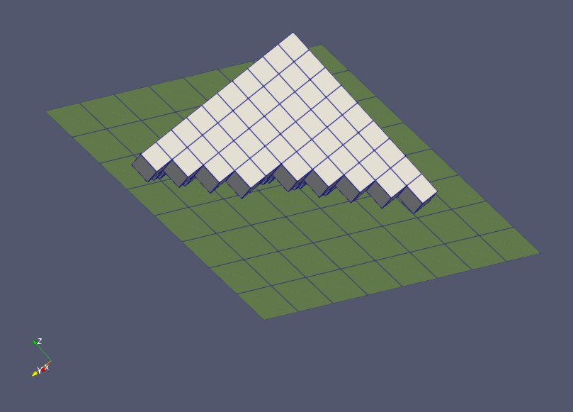
Fig. 5.21 Invert the orientation of the clipping plane
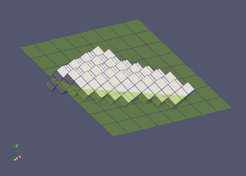
Fig. 5.22 Keep only those blocks (cells) that are cut by the clipping plane
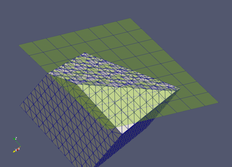
Fig. 5.23 Clip also the blocks (cells) of the model - with the effect that they are not any more cuboids
5.4.2. Shaping a Block Model
Normally, block models are assumed to be generated with other tools for further processing with AthosGEO View and AthosGEO Blend. However, it is possible to generate simple block models also “manually”, with the help of AthosGEO View. This includes the initial generation with the Block Model source, and assigning attributes with the different attribute assignment filters.
On top of that, we want to adapt the shape of the model to the volume that we want to cover. However, the Clip Geometry filter only deals with the geometry, but not with the specifics of a block model with it’s typical attributes and attribute types (see Section 6).
Example: Cutting a block model should keep the blocks intact, which we can achieve also with the Clip Geometry filter without the Clip the cells option. But along the boundary, we will certainly have blocks with reduced tonnage, and this cannot be handled with the Clip Geometry filter: This is the domain of the specific block model clipping filters.
5.4.2.1. Clip Model with Boundary  
The function of the Clip Model with Boundary filter is that of a “block model cookie cutter”. Input is a block model and a closed boundary line (polyline) - see Fig. 5.24.
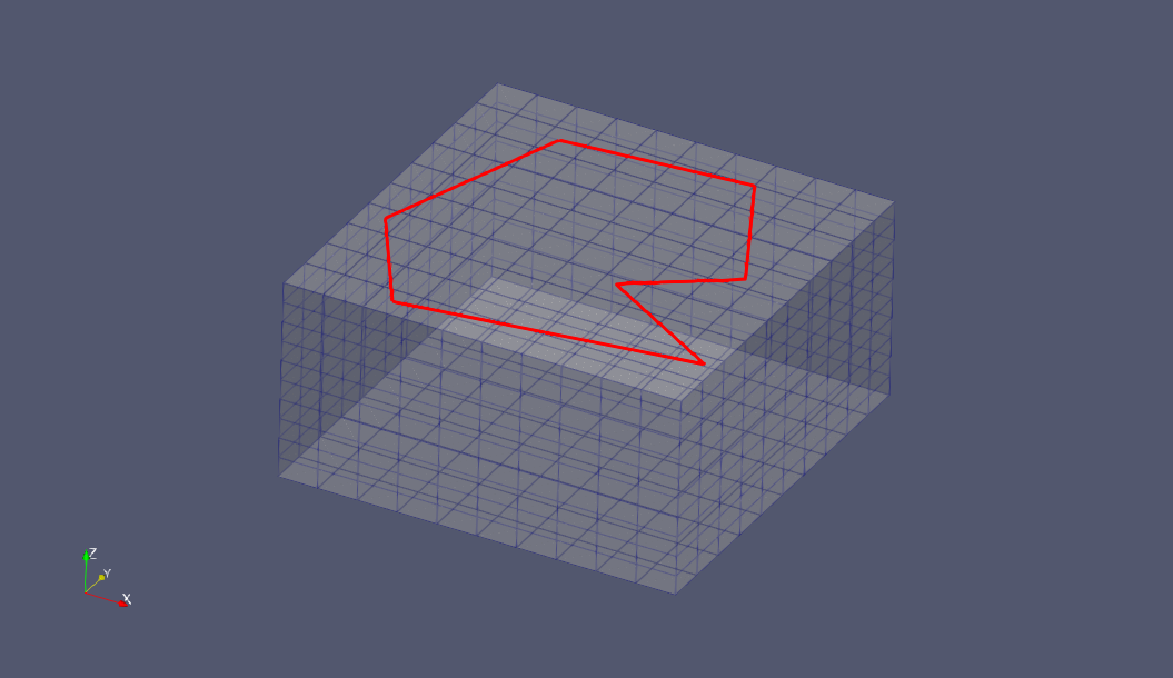
Fig. 5.24 An “empty” block model (in this case generated with the Block Model source) and a polyline (generated with the Poly Line source), to be used as input for the Clip Model with Boundary filter
The result of the clipping can be seen in Fig. 5.25. Part of the resulting block model is also shown in tabular form in Fig. 5.26. You see there that not only the KTons attribute was adapted to the fraction of a block inside the boundary line, but also a new attribute VolFactor was generated that reflects the percentage of the block that is part of the model.
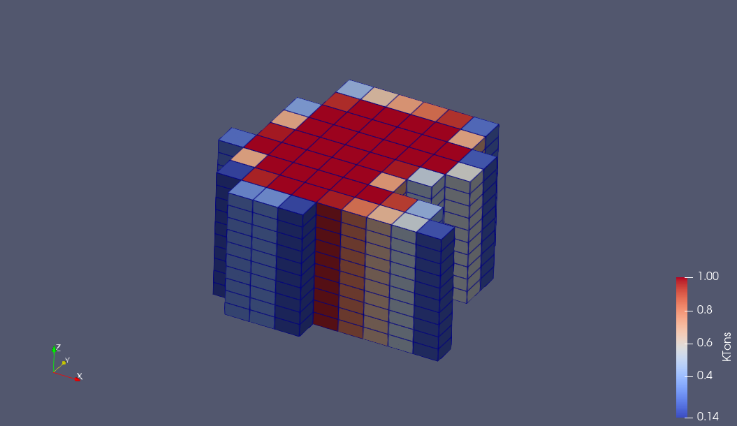
Fig. 5.25 Initially, all blocks in this artificial example model had a tonnage of 1 KTons. After clipping with the boundary line, tonnage of each block was adapted in such a way to reflect only the tonnage that is inside the boundary line, while the shape of the blocks were not changed.
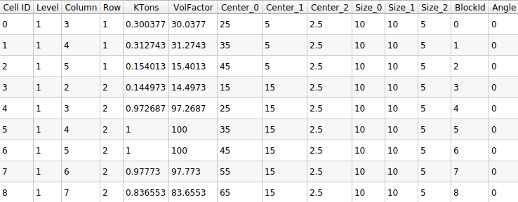
Fig. 5.26 The tabular display of the clipping result illustrates the fact that existing attributes are handled according to their meaning, and an additional VolFactor attribute is added if it does not exist yet
Hint
The Minimum Retained Volume Factor option allows to discard those blocks that would contain only a very small fraction of the original block tonnage. Set this to 0 if such a behaviour is not allowed, or to some pragmatic low value like 10%.
Regarding the Respect Preceding Horizontal Clip option, please see the following section Clip Model with Surface
5.4.2.2. Clip Model with Surface  
The Clip Model with Surface filter is intended for adapting a block model to a real topo surface from above (with option Keep Blocks Below the Surface turned on), or cutting it from below at some underground limit (same option turned off). Input is a block model and a triangulated surface (in the sense of a “topo surfac” or “2.5D surface”), as shown in Fig. 5.27, and the result would be like shown in Fig. 5.28.
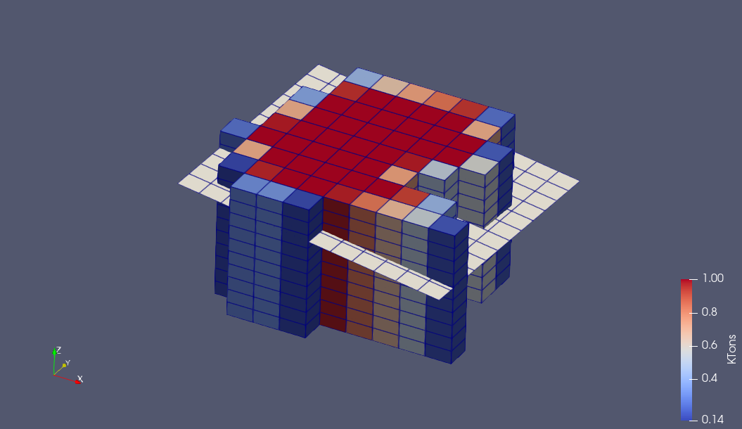
Fig. 5.27 The clipping surface of the model is supposed to be of type “2.5D”, with no more than one value of Z referring to every (X, Y) coordinate pair
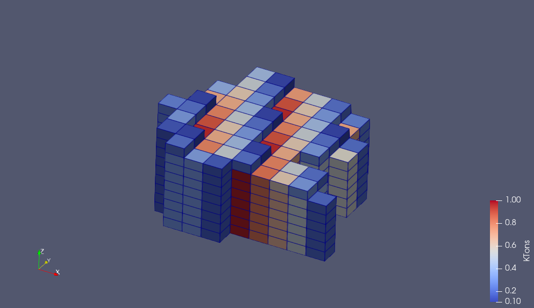
Fig. 5.28 Like with the Clip Model with Boundary filter, also this filter will handle attributes according to their meaning, like adapting the tonnage of a block to the volume fraction that remains inside the block model after clipping, while leaving the shape of the blocks unchanged
Hint
The Respect Previous Vertical Clip option has an effect if the input block model already has a VolFactor attribute from a previous clipping operation. The problem is that the filter cannot “know” from with side of a block any previously clipped volume was removed, so some simplifications must be made - and the user needs to give a hint in order to make the approximation a little bit more reliable.
The assumption is that we have two cases to distinguish:
The volume factor reduction is the result of a previous vertical clip, i.e. the application of a Clip Model with Boundary filter:
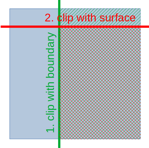
The volume factor is an update of a previous horizontal clip, i.e. the application of a Clip Model with Surface filter:
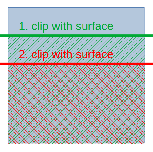
In the first case, the resulting VolFactor can be found by a multiplication of the old with a new volume factor, while in the second case, the result will be simply the smaller value of the two
5.4.2.3. Clip Model with GeoTiff  
This filter is similar to using the Clip Model with Surface filter, except for the fact that the filter asks directly for a GeoTIFF file as a property that describes the topo surface to be used. The result would be something like shown in Fig. 5.29.
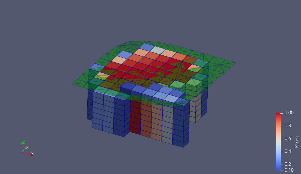
Fig. 5.29 This model is clipped directly with a GeoTIFF file. The same file has also been loaded with the GeoTIFF Reader, for illustration purposes: that step is not required for the functionality of the clipping filter.
5.4.3. Precise Topo Cutting  
The Clip Geometry filter described above in Generic Clipping is not designed to clip a top surface with maximum possible precision, as can be seen in Fig. 5.30 and Fig. 5.31.
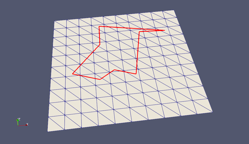
Fig. 5.30 A triangulated surface that symbolizes a topo surface, and a polyline boundary line. The purpose is to use the boundary to clip a “hole” into the topo surface, in a “cookie cutter” style
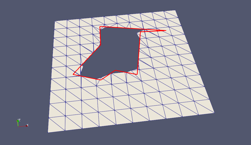
Fig. 5.31 The cookie cutting job as defined in Fig. 5.30 can be done with the Clip Geometry filter, and the result will be as shown here
It is obvious that the punched hole is not following the boundary input line precisely. However, if the required geometric resolution of the topography is defined by the input triangles, the approximation does not look unreasonable.
If a higher resolution is needed, it is possible to apply the Subdivide filter to the topo, the geometric resolution will be increased, and the punched hole accordingly - as can be seen in Fig. 5.32.
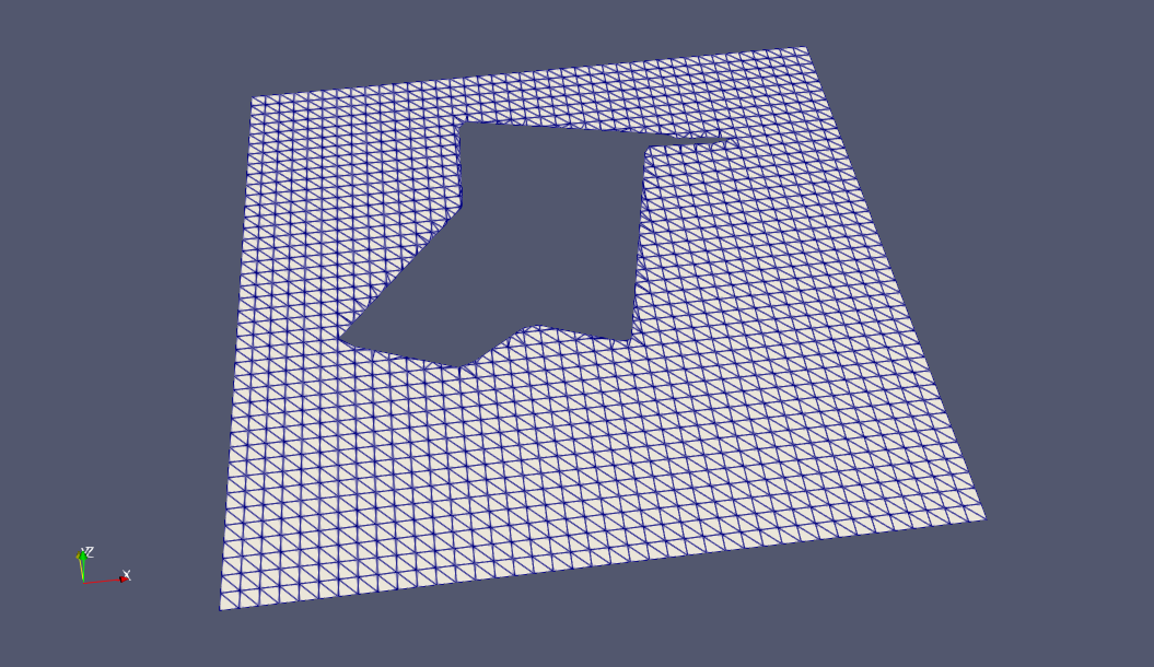
Fig. 5.32 After application of the Subdivide filter to the input topo, the Clip Geometry filter will generate a result with much higher geometric resolution than shown in Fig. 5.31
With all the above background, it is immediately obvious how the Topo Cutter filter is working with a very different algorithm: see Fig. 5.33.
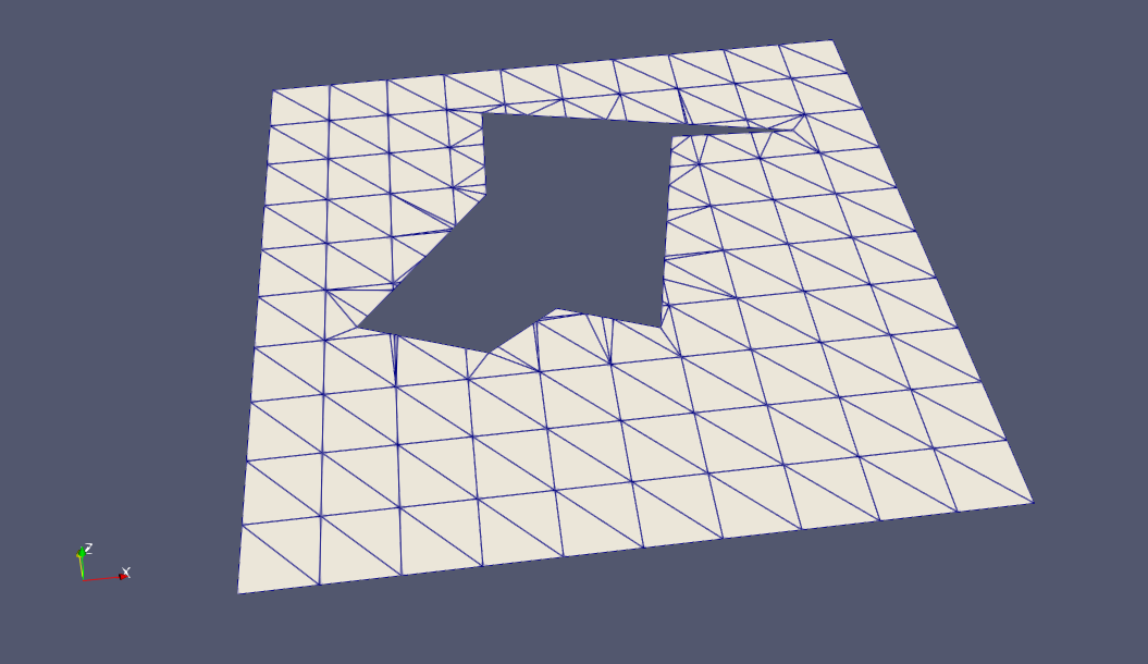
Fig. 5.33 The Topo Cutter filter cuts every single triangle in the best possible manner with the input boundary
The difference in strategy can be summarized in two points:
Clipping is done triangle by triangle in a way that the boundary line is followed exactly. This includes even cases where we have more than one closed boundary, and even if closed boundaries are nested within each other, as shown in Fig. 5.34. (Exception: self-intersections are not allowed.)
No clipping algorithm will ever be 100% perfect in all situations. While Clip Geometry is not as precise as possible, it tends to be very robust. The Topo Clipper, on the other hand, tries to do it’s best regarding precise clipping, but in some special cases it fails: Adapt the Delaunay Offset and/or the Number of Points to Insert properties.
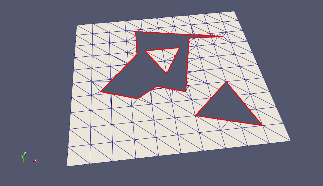
Fig. 5.34 With the Topo Cutter, a boundary can consist of several closed polylines that may even be nested. Only (self) intersections are not allowed
5.4.4. Outline Block Model  
The Outline Block Model filter is a complement for the Topo Cutter filter described above if the purpose is to cut a hole into a topo surface that matches a block model precisely. The block model outline will be generated at a Z value of 0, as shown in Fig. 5.35. It is directly useable as input for the Topo Cutter filter.
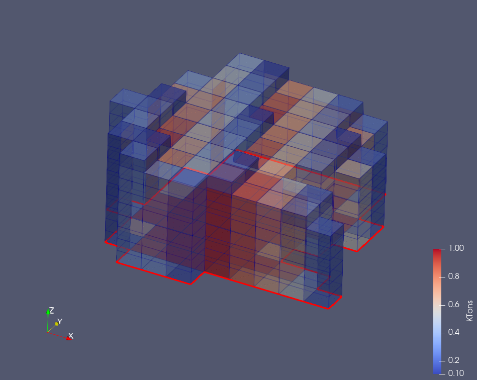
Fig. 5.35 The Outline Block Model filter.